Showing posts with label helicopter. Show all posts

Saturday, October 16, 2010

Helicopter SAS: Overview

This post will be an overview of my helicopter Stability Augmentation System (SAS) project.

The Story


This last spring, I decided to build a stability augmentation system (SAS) for an R/C helicopter, with the goal of giving my dad an easy-to-fly R/C helicopter that still had the coolness factor of a single-rotor design.

I spent the next two months designing, building, and debugging the SAS. I don't think I could have flown the helicopter without the SAS active, but then again I haven't tried.

I did crash it a few times, though, and the unbalanced blades and bent shafts definitely degraded performance. I also broke the landing gear and cyanoacrylated it back together. During my demo for my dad (my family came to town for graduation), I touched down too hard and one side of the landing gear broke, causing the helicopter to flop over onto that side.

My dad took it home; I think he's repaired the crash damage but I don't think he's flown it. So, I haven't been quite successful in that regard. Maybe next time...

The Parts


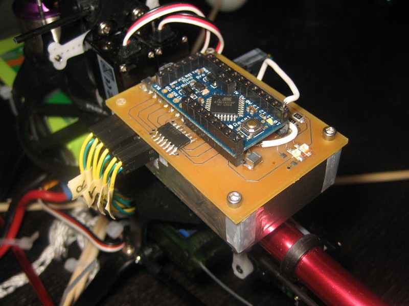
The SAS is implemented as this foil-shielded box that sits where the original heading-hold gyro used to be. Inside the box are sensors to measure the helicopter's motion and orientation. The lid of the box is the control board that uses those measurements to send stabilizing control signals to the helicopter servos.


Barely visible in this photo is the wireless module taped to the rear strut of the right (starboard?) landing skid. I used the telemetry data extensively during testing and debugging.

Suggestions for Next Time


  • Velocity feedback (optical flow)
  • Heading measurement (magnetometer w/ offset for body-fixed fields)
    • Transformation of cyclic commands from pilot axes to body-fixed axes
  • Different mounting location/method to minimize vibration at accelerometers
  • Don't crash it as much

Thursday, October 7, 2010

Helicopter SAS: Control module

This post will describe the main control module of my helicopter stability augmentation system (SAS).

Summary


This is the main control board of the SAS. It sits between the helicopter radio receiver and the servos, interpreting the servo commands from the receiver and adding a stabilizing input before relaying these commands to the servos. It operates using feedback based on helicopter orientation information from the AHRS module.

Hardware


The module consists of an Arduino Pro Mini 328 (3.3V, 8MHz) mounted on a board I designed (fabbed by AP Circuits). The Arduino is connected as follows:

Arduino pinATMega328 pinConnected to
2PD2Servo in (left cyclic)
3PD3Servo in (front cyclic)
4PD4N/C
5PD5Servo in (tail)
6PD6Servo in (gyro control)
7PD7Servo in (right cyclic)
8PB0 (ICP1)Accessory header
9PB1 (OC1A)Shift register Clock
10PB2 (SS)White wire to AHRS
11PB3 (MOSI)AHRS header
12PB4 (MISO)AHRS header
13PB5 (SCK)AHRS header
A0PC0Shift register Data
A1PC1Red LED
A2PC2Shift register Clear
A3PC3Green LED
A4PC4 (SDA)Accessory header
A5PC5 (SCL)Accessory header
VCCVCC, AVCCN/C
GNDGND, AGNDGround
RAWN/A+5V
DTRPC6 (RESET)Programming header
RXIPD0 (RXD)Programming header
TXOPD1(TXD)Programming header

Since the helicopter runs at 5V and the SAS at 3.3V, all inputs are buffered through a 74LS07D 3.3V hex buffer with 5V-tolerant inputs, and the outputs are driven by a 74HCT164D 5V 8-bit shift register with TTL-compatible inputs.

The only other components on the board are a 3.3V linear voltage regulator, some bypass capacitors, and two LEDs.

Communications


Under normal operation, the SAS main board communicates with the Attitude and Heading Reference System (AHRS), helicopter radio receiver, and helicopter servos. Furthermore, it has connections for programming/debugging and a few extra pins that are not currently used.

AHRS

Since the AHRS module's SPI SS pin is not externally accessible, this board was originally designed not to connect the SS line. However, this ultimately proved infeasible, so there was some scraping of traces and now there is a white wire that connects from an AHRS digital output (the AHRS is the SPI master) to the Arduino's SS pin.

The other SPI lines (SCK, MISO, MOSI) are connected normally. This board also supplies the AHRS module with 5V power (AHRS module has on-board 3.3V reg).

Helicopter radio receiver

The helicopter radio has six output channels: 3 for cyclic servos, 1 for the tail servo, 1 for the motor speed controller, and 1 for gyro gain control. As a failsafe measure, the motor speed control channel is connected directly to the receiver, bypassing the SAS altogether. The other 5 channels are connected to Arduino digital inputs.

These servo signals are encoded using pulse width modulation (PWM). The range 1 to 2 ms nominally corresponds to the servo limits of travel. The radio receiver generates a pulse on each channel sequentially and refreshes at approximately 50 Hz.

The radio receiver also provides this board with 5V power.

Helicopter servos

The SAS communicates with the helicopter servos using the same PWM scheme. Since only one pulse will be active at a time and the pulses can be sent sequentially, the 74HCT164 shift register (no latch) is well suited for this application. This allows us to control up to 8 servo channels using 3 digital outputs with no loss of functionality.

Since servos can draw a lot of power, the servo power supply lines are not routed through the SAS module.

Programming/Debugging

In order to facilitate programming and debugging, the main board also brings out the UART's RX and TX lines. The RESET pin is also connected to the serial port DTR line via a high-pass RC circuit (on the Arduino). This is used during programming to activate the Arduino bootloader before transferring code.

The programming/debugging header also provides 3.3V power for a wireless module.

Other connections

The SAS main board also brings out the Arduino's ICP1 (input capture on timer 1) pin. This could be used with a main shaft encoder to measure rotor speed, but that hardware was never implemented.

The I2C bus (SDA and SCL) is also available in the accessory header, but so far there is nothing to connect to it.

Control law


A quick note on terminology: the "control law" is the algorithm used to calculate the "control output" (signals sent to helicopter servos) based on the "command input" (signals from helicopter radio receiver, which originated from the human pilot via radio transmitter) and feedback from the AHRS. The servos change the angles of the helicopter blades, generating aerodynamic forces and moments that act on the helicopter. The resulting rotations and accelerations are measured by the AHRS.

The goal of the SAS is to produce control outputs to return the helicopter to upright (pitch and roll angles = 0) and not spinning (yaw rate = 0). If the pilot sends a command input, then the SAS should add that to the control output, and it should not be too obtrusive about it.

In order to keep things simple, I attempt to control each axis independently of the others.

AxisActuatorControl law
Pitch (tilt up/down)Cyclic (long.)u = c - KPθ - KDω
Roll (tilt left/right)Cyclic (lat.)u = c - KPθ - KDω
Yaw (turn left/right)Tail rotoru = ( KP + KI / (τIs+1) + KDs/(τDs + 1) )(c - ω)
LiftCollectiveu = c (no feedback)
Rotor speedThrottleu = c (physically bypasses SAS)

The control laws in the table above should be read as schematic representations of the type of control law used, not the actual formulae used to calculate control output. u is the control output, c is the command input, θ is the orientation angle, ω is the rotation rate, s is the Laplace...thing (variable? argument?), K's are gains, and τ's are dynamic compensator parameters.

System identification

In this case, the complexity of the control law was limited by the quality of the system identification. There exists significant coupling between axes and all sorts of interesting modes involving combinations of rotational and translational motion. The literature describes what coefficients would go into a state-space model to capture these dynamics, but I simply didn't perform the measurements necessary to measure these effects.

In the literature, system identification is performed by getting a competent pilot to input a frequency sweep while keeping the helicopter under control in near-hover conditions. This was a Catch-22 for me; if I could pilot the helicopter well enough to do this, I wouldn't need to design a control system!

For me, system identification consisted of programming the SAS to output a frequency sweep on each actuator sequentially, then holding the helicopter by the skids at arm's length and praying for my safety as whirling blades of death heaved to and fro with surprising unpredictability. There is a tradeoff here between holding the helicopter lightly so as not to influence the measurement and holding the helicopter firmly so that it doesn't whack you in the face during the low-frequency portion of the sweep. And now that I've seen what a crash can do to a 3mm steel rod, I'm not sure I'd use this method again.

After risking life and limb to carry out these experiments, I transformed the telemetry results into the frequency domain and estimated two first-order models for pitch and roll and a second-order model for yaw.

Software functional description


Much of the coding frustration associated with the SAS involved dealing with non-negligible communication and computation latencies. Rather than step through the various code modules, I will describe some of the more interesting interactions between modules.

Maintaining timing accuracy with multiple interrupts

Receiving data from two asynchronous sources (AHRS and radio receiver) proved to be a challenge. The Arduino needs to accurately measure the servo command input pulse widths. Since there are not enough input capture channels, I implemented this measurement using the pin change interrupt, which can be configured to be triggered by an edge on any of the servo input pins.

However, the Arduino also needs an interrupt service routine for communications with the AHRS (as the SPI slave, it needs to respond within 32 μs of a received byte). Since this may conflict with the input servo pulse timing, this ISR needs to be kept as short as possible. By hand-optimizing of the ISR prologue, I trimmed it down to 46 clocks (5.8 μs).

Servo control output is also interrupt-driven: we shift a single high bit into the shift register and then use the timer module (output compare pin A) to produce correctly-timed rising edges on the clock line, thus sending sequential pulses to the servos. Since servo output never overlaps with servo input, this interrupt does not conflict with input pulse timing.

Interrupts, queues, and normal-priority routines

In order to keep the interrupt service routines as short as possible, they interact only with queues and perform the minimum amount of processing required. Further processing of the data is performed in a normal-priority routine called from the main loop.

Function Interrupt source ISR Normal-priority routine
Servo input Pin change Push current timer value and pin state onto queue. Pop pin states and timer values off queue; calculate pulse duration for the associated channel(s). Update global servo input array and flag the channel(s) as having been updated.
AHRS input SPI serial transfer complete Push received byte onto queue. Check if a full 38-byte frame has been received. If so, pop bytes off queue and re-cast into correct data type. If checksum is correct, update global helicopter orientation arrays.
Servo output Timer 1 output compare match If queue is empty, disable interrupt. Otherwise, pop next pulse duration off queue and add to output compare register. Set data pin high to shift out a single high bit. Enqueue desired pulse durations, set the output compare register to 50 μs from now, and enable interrupts.

Sending telemetry over the serial port also involves a queue structure. However, since it is an auxiliary task, it does not get the privilege of its own interrupt. The dequeue function, which checks if the UART is ready and pops the next character into the transmit register, is called from the main loop. This is less efficient, but prevents further interference with the critical servo input timing.

Main loop description

The main loop performs the following tasks:
  1. Call the AHRS input routine. If it indicates that a full data frame has been received:
    1. Calculate the feedback portion of the control law using the newly-provided orientation and rotation rate data.
  2. Call the servo input routine. If it indicates that a full servo update has occurred:
    1. Calculate the feedforward portion of the control law using the new servo commands.
    2. Check the "gyro control" servo channel:
      1. If < 0, this indicates the "Gyro enable" switch on the radio transmitter is in the "1" position. Sum the feedforward and feedback portions of the control law to get the SAS control output.
      2. If > 0, this indicates the "Gyro enable" switch is in the "0" position. Set the control output equal to the command input (i.e., don't add any additional control).
    3. Call the servo output function to begin sending pulses.
  3. Check if 20 ms has passed since the last telemetry update. If so:
    1. Begin formatting and queuing telemetry data to be sent. This actually takes a significant amount of time. In order to give the other routines a chance to update, this is broken into 4 tasks that will be performed over the next 4 main loop iterations.
    2. Update LEDs based on whether the AHRS (green LED) and servo input (red LED) have updated since the last telemetry cycle.
  4. Call the serial port dequeue function to send the next byte of telemetry data, if the UART is ready.
This order of event handers ensures the control algorithm is always using the most recent information. Breaking up the control law calculations reduces the average latency between receiving a servo command input and issuing a servo control output.

Sunday, October 3, 2010

Helicopter SAS: AHRS module

This post will describe the AHRS (Attitude and Heading Reference System) module of my helicopter stability augmentation system.


Summary

The AHRS provides the sensing component of the stability augmentation system (SAS). It estimates the helicopter's orientation using measurements from the onboard accelerometer and gyro. Ever 20 ms, it reports an updated estimate to the SAS main board over an SPI serial interface.

Hardware


This section describes the hardware and communications connectivity of the AHRS module.

The AHRS uses an unmodified SparkFun 9 degree of freedom Razor IMU (rev 14, with the 8Mhz ATmega328P). The board comprises:
  1. ATmega328P 8-bit microcontroller with 8 MHz clock
  2. 3-axis accelerometer
  3. 2-axis (pitch/roll) and 1-axis (yaw) gyros, with 48 Hz lowpass filter
  4. 3-axis magnetometer
  5. 6-pin header for Sparkfun's FTDI USB-UART breakout board
  6. 6-pin header for ICSP
  7. 2-pin header for unregulated power supply
The microcontroller interfaces with the accelerometer and magnetometer via I2C and with the gyros via its ADC channels. The UART header brings out the RX and TX pins. The ICSP header brings out the the SPI MISO, MOSI, and clock pins, but unfortunately not the slave select pin, so we can only operate the SPI module in master mode.

Under normal operation, the AHRS communicates with the SAS main board over SPI. The UART module is disabled and the RX pin used as a digital output to drive the SAS main board's SPI slave select pin. That is the purpose of the white wire in the photo at the top of this post. 

The AHRS board is mounted inside a polycarbonate enclosure wrapped in aluminum foil. When the main board is installed on top of the box, its ground plane makes contact with the foil, creating a shielded environment for the sensors.

Estimator Algorithm


This section describes the quaternion-based kinematic estimator implemented as a first-order linear complementary filter between gyro measurement of rotation rate and accelerometer measurement of gravity vector.

The purpose of the AHRS is to provide estimates of rotation rate, orientation, and translational acceleration to the SAS. The gyros directly measure rotation rate, but the accelerometers measure a combination of gravitational and translational acceleration, so we need an estimator to separate the two. For now, we are not using the magnetometer because the local magnetic fields from the helicopter's motors disrupt the measurements.

First, the sensor measurements are filtered with an 8 Hz (50 rad/s) first-order digital lowpass filter. This helps mitigate the noise (mechanical vibration) produced by the main rotor. Combined with oversampling (estimator loop runs at 50 Hz, but gyros are sampled at 500 Hz and accelerometer at 200 Hz), this also increases measurement resolution, but that's a moot point given the low signal-to-noise ratio in flight conditions.

Unlike a dynamic estimator, which uses the dynamic equations of motion (F = ma), a kinematic estimator uses only kinematic equations (v = dx/dt, a = dv/dt). In this case, we estimate orientation (rotation angles) from gyro measurements (rotation rates) and gravity vector measurements (rotation angle error). Implemented in discrete time, the estimator looks like:
  1. At time t1, we have an estimated orientation q1, a quaternion representing the rotation of the helicopter from its reference position to its current orientation. Therefore q1 also represents the transformation from body-fixed axes to inertial axes, and q1-1 the transformation from inertial to body-fixed.
  2. We can predict that the gravity vector, measured in body-fixed axes, will be gpred = q1-1g0q1, where g0 is the gravity vector in inertial axes, i.e. [0;  0;  1].
  3. The actual accelerometer measurement ameas gives us two things:
    1. First, the translational acceleration is simply the residual acceleration: atrans = ameas - gpred
    2. Second, assuming atrans averages out to zero, our measured gravity vector is simply our measured acceleration, normalized to one gee: gmeas = ameas/||ameas||
  4. Thus, step 3.2 gives us one estimate of orientation error: for small angles, Δθgrav = gmeas × gpred, where Δθgrav is the additional rotation we need to apply to q1 in order to bring the predicted gravity vector in line with the measured gravity vector.
  5. However, our rotation rate measurements give us another estimate of orientation error: Δθgyro = ωΔt where ω is the gyro rotation rate measurement.
  6. This is where the complementary filter steps in. For a crossover frequency fC << 1/Δt, the update law Δθ = Δθgyro + (2πfCΔt)Δθgrav is equivalent to low-passing Δθgrav at fC, high-passing Δθgyro at the same frequency, and summing the two filtered values, an operation that preserves unity gain and zero phase over all frequencies.
  7. For small angles, we can update the quaternion using the operation:
    q2 = [1;  Δθx/2;  Δθy/2;  Δθz/2] × q1
  8. We can then report rotation rate (ω, measured), orientation (Euler angles derived from q), and translational acceleration (atrans, from step 3.1) to the SAS main board.
I chose a crossover frequency fC = 0.1 Hz (0.6 rad/s) as a balance between the evils of offset drift in the rotation rate measurements (mitigated by high crossover frequency) and translational acceleration transients in the gravity vector measurements (mitigated by low crossover frequency).

Software Implementation


The AHRS code is divided into several modules: a main module that calls the necessary functions from the other modules, a kinematic estimator module that implements the algorithm described above, and low-level input, ouput, and math modules.

Main module

One of the funny things the Arduino IDE does is it takes your .pde source files and puts them all into one file and auto-generates a header file before compilation. On the one hand, you don't need to write your own header files, but it also means you can't use keywords like "static" to manage access control (because everything ends up in the same file anyways). So I decided to be lazy and just make all the vector and matrix variables global. They are declared in the main module.

The main module also contains:

setup(): Calls the other modules' initialization functions

loop(): Called whenever the processor is free; it polls the Arduino library millis() function to run a 50 Hz update. The loop body consists of calling the 3 sensor update functions (gyro, accelerometer, and magnetometer), the estimator update function, and finally the data output function.

Estimator module

estimator_init(): Takes an average of a bunch of gravity vector measurements to create a reference vector for the "zero" orientation.

estimator_update(): Calls the low-level math routines to carry out the algorithm described above.

Input modules

I2C module: This is a C library I wrote as an alternative to the Arduino library's supplied I2C module. In order to write data, you supply the module with an I2C address, a pointer to a flag byte, and the data you wish to write. The module copies the data into an internal buffer, begins the writing process (done through hardware), and returns. The ISR makes sure your data gets sent and sets your flag when it's done. To read data, you pass it a pointer to a read buffer. The ISR populates the read buffer as data comes in, and sets your flag when it's done. This way, multiple sources can all access the I2C module at the same time, and nobody has to wait on the hardware.

Sensors module: The sensors are all read and filtered on their own loop (a 1 kHz timer ISR), separate from the main loop. The gyro (an analog input) is read at 500 Hz and the accelerometer (I2C interface) at 200 Hz; both are filtered with an 8 Hz digital lowpass filter. When the user asks for sensor data, the module returns the most recent filtered values (within a global interrupt disable/enable block).

Output modules

SPI Master module: This is a pretty straightforward module implementing blocking code to send a 38-byte data frame from the AHRS to the SAS. Unlike the I2C module, which is called from within an interrupt, it is okay for this code to hold up execution. The data frame consists of a start-of-frame byte, 9 floating point values (Euler angles, gyro rates, and translational accelerations), and a checksum byte.

Serial output module: This is only active in debug mode; it calls the Arduino library Serial.print() functions to send AHRS results and raw sensor readings as ASCII text through the UART module.

Math modules

Vector module: Contains some very straightforward functions for vector addition, scaling, and dot and cross products. Also the fast inverse square root routine, for vector normalization.

Matrix module: Matrix multiplication, and a function for turning a rotation matrix into Euler angles.

Quaternion module: Functions for quaternion scaling and normalization, rotating a quaternion by body-fixed Euler angles, and converting a quaternion into a rotation matrix.

Sunday, June 13, 2010

Updates from the past week

Abbreviated posts:

Saturday (6/5)
Helicopter test flight with Aaron and Max. Had some close calls myself (lost track of heading and then the wind took it far away where I couldn't see it very well), but managed to keep the blades away from danger. Let Aaron fly it. He's got some co-axial experience and some simulator time (well, 5 minutes worth), and was much better at holding a hover than I was. Unfortunately ended with crashing into a bike tire. Broke the landing gear.

Glued the landing gear back in place, replaced the feathering shaft (dunno exactly when it got bent). Lately have been seeing the system act glitchy; I don't know why and I don't even know where to start looking. The most plausible scenario I can think of is the increased vibrations (due to unbalanced blades or other damage) putting excessive noise into the AHRS.

Tuesday (6/8)
A rasbora died! :( It was the loner fish who looked like he had tail damage, possibly as a result of fights. His tail was completely gone when I found him. And that morning, the other fishes were strangely quiet (they usually fight in the morning), huddled together in the center of the tank.

Wednesday (6/9)
Muir Beach and pirates' cove with Max, Bryce, and Nick. A really windy spot. I climb a boulder. Throwing rocks. Fiji water and expensive sammiches from JJ&F.

Thursday (6/10)
Old oto (a.k.a. fat oto) died :( Afterwards, we changed the water, because that's all that we really can do, but water tests didn't show anything particularly out of the ordinary. But it is a troubling spate of fish deaths. While changing the water, did notice the thin tube (between the two tanks) was clogged by a wayward snail.

Friday (6/11)
Family (parents and brother) in town! Presented the helicopter to my dad. Took it out for a test run, but ended up crashing the landing. I think it was a level landing, just a little hard, and then the previously-broken landing gear broke, causing the helicopter to roll over on that side until the blades struck the ground. Feathering shaft is noticeably bent. Damnit. Felt pretty bad about it all.

Went to Mediterranean Wraps for lunch, then made beef Stroganov for dinner. Used beef flank this time, which I didn't like as much as the tenderloin we used last time. Also had watermelon, which was a great treat in the hot weather.

Saturday (6/12)
Went up to Muir Woods and walked around (Hillside trail, ~2 mi). Big sequoias. Very straight. Asexual reproduction through burls, which cause a ring of clonal redwoods to grow around the burnt-out stump of the parent. Also, bendy phototroping bay laurels, which seem to be able to grow out of dead logs. And redwood sorrels, which sleep in the sun and open up in the shade (except for some lazy ones we saw napping in the shade).

The hilly drive up put higher demands on the engine than I'd seen before. Even on the highway, there were parts where full throttle in fifth just wasn't enough (well, not quite WOT...I wanted to avoid the rich burn and other power-boosting tweaks that happen up there).

This whole weekend I've been feeling the car act a little more sluggish than usual. Due to the high correlation between input variables, I can't tell whether this is due to increased passenger mass (~15% of the vehicle weight) or the air conditioner load. Actually, now that I think about it, in addition to slower acceleration, I've also noticed longer stopping distances (which can only be explained by increased mass). An unrelated observation: the A/C is more powerful at higher engine speeds.

Also went to the Golden Gate Bridge visitor center, and the Richmond district's Chinatown. Came back to have dinner with family friends at Jade Palace/Duck restaurant.

Sunday (6/13)
Got up early to get a Master's hood from the bookstore. Graduation today! Turns out the Master's robe is slightly different from the Bachelor's: it's got extensions from the bottoms of the sleeves, as if you might have 2 forearms like the Gatekeepers from Schlock Mercenary. Skipped the commencement ceremony, though; just went to the department ceremony.

Afterwards, went to the San Jose Tech Museum; it was free second Sundays, which was cool, and we spent the whole time going through the exhibits. Not much new since the last time I've been there (there was a Genghis Kahn exhibit, but it was kinda expensive and the rest of the family wasn't very interested), but it was much less crowded than I've seen before, which was nice.

Oh - check engine light came on again; still the neutral position switch and knock sensor, so I just cleared it again.

Friday, June 4, 2010

Helicopter repairs

Parts arrived Wednesday! Very fast shipping: I ordered on Sunday, shipped out from Hong Kong on Monday (well, still Sunday by GMT+8:00 "Pacific" time), got delivered to my house on Wednesday. And all that for $25. So why does it cost $30 to get something overnighted from Oakland? The mysteries of international shipping...

Anyways, hit up hardware stores looking for a 5.5mm nut driver and got laughed out. Finally ordered it from McMaster. Since the nut is recessed deep inside the blade clamp, you need a nut driver with a small OD. 53965A17 is the smallest McMaster has (OD .318" = 8.0 mm), followed by 6919A13 (OD .343" = 8.7 mm), which just barely fits in the blade clamp. The power driver (8534A52) is way too big, and I didn't try out the hollow-shaft nutdriver (7299A19).

That arrived Thursday. The actual repair was very simple; took about 10 minutes. You can see the damaged shafts below: flybar (top) and feathering shaft (bottom).
For size reference, that's an M3 thread on the feathering shaft. The rubber mounting rings on the feathering shaft are damaged, too, but I don't have a replacement so I just stuck it back in. After repair I had to adjust some linkage lengths (just needed 2 turns) to get the two new blades to rotate in the same plane.

Today I flew; everything is fine. I got some sustained hovers and decent landings, which is pretty exciting. Need to do something about the yaw controller at takeoff: the integrator builds up angle error while it's on the ground, so when it lifts off there's a huge rudder command which causes the helicopter to whip around until it's in what it thinks to be zero angle error. Pretty disconcerting.

The goal, though, is not for me to get better at flying, but to improve the control system. So I put in some frequency sweeps (telemetry is working better now), which again was a really bad idea in my small parking lot surrounded by trees and fences. Caught a fence with a blade tip and was down for the count.

Damage report: blade tip smashed up a bit; not too bad. Swashplate popped out of the anti-rotation bracket; that was an easy fix. Flybar might be bent; hard to tell, so I won't reject the null hypothesis of "not bent". The two halves of the helicopter chassis split at the main shaft top bearing; this also happened last time and I think the threads in the plastic are stripped now. Maybe okay to ignore; otherwise will need a longer screw to go through the stripped half and into a nut.

Tried replacing the damaged blade with the un-damaged blade from the previous crash, but the blades are sold in balanced sets and mix-and-match don't work so well. So I kept the damaged blade. Needed to re-adjust linkage lengths to get the blades rotating in the same plane, and added some aluminum foil tape to the damaged blade in an amateur attempt at blade balancing.

Flew again this afternoon. Blades aren't as well balanced as they were pre-crash, but that doesn't seem to affect things too much at flight conditions (though we do see much more wobble while the rotor is spinning up or down). More flying (this time in a larger space) tomorrow.

Monday, May 31, 2010

Helicopter SAS: A summary

This post is meant to be a summary of my helicopter project so far.

Purpose


My dad likes R/C helicopters. Well, the idea of them, anyways. The truth is, he doesn't have the patience to learn how to fly one, at least not one of the cool single-rotor ones. So the project is to create an electronic stability augmentation system (SAS) that would sit between the helicopter radio receiver and the servos to provide some additional stabilizing control input.

April 5 to 16: Planning and Preparations


Picked out sensors (SparkFun's "Razor" IMU unit with accelerometer, gyro, and magnetometer), control board (Arduino Pro Mini), and helicopter (E-sky King 3, a cheap, 600mm rotor diameter, collective pitch helicopter with modular electronics). Brainstormed potential ways to measure velocity. Wrote some Arduino and MATLAB code to function as an oscilloscope so I can look at servo pulses.

April 18 to 28: First Impressions


The sensor board has an 8-bit Atmel microprocessor on board, so the plan is to have it run the estimator algorithm, i.e. function as an Attitude and Heading Reference System (AHRS). Played with the sf9domahrs code very briefly before deciding that I didn't like it and could do better. Changed the internal angle representation from rotation matrix to quaternion, increased the sensor update frequency and made the update code non-blocking. Started on an Extended Kalman Filter but had a hard time casting each sensor's particular brand of uncertainty into the Kalman paradigm, so ended up doing pole placement on a quaternion-based linear kinematic estimator that incorporated all 3 sensors (gyro, accelerometer, magnetometer).

Got the helicopter in the mail; completely ready to fly out of the box (well, had to charge the battery and install my ping-pong ball landing gear, but that was it). Did a test flight that mainly consisted of skittering across the parking lot on the ping-pong balls, but I did get some good insight into the dynamics for the few seconds I actually had it completely off the ground. I think the primary take-away point was that having to close a control loop from cyclic input to attitude was too much pilot workload for me, and that simply having attitude track the cyclic stick would be a huge step in making it easier to fly.

April 29 to May 15: Hardware


Designed a circuit board that would interface the Arduino, sensor board, helicopter, and wireless (XBee module, for telemetry) hardware all together.
Pretty simple: it's got some level shift chips, voltage regulator, capacitors, and some LEDs. Tried to keep the back as solid as possible, as this board serves as the top for the shielded box enclosing the sensor board.
Putting everything together involved porting the AHRS code from MATLAB to the AVR microprocessor, writing the serial communications code, machining the box out of polycarbonate, and assembling everything. In the process, I came across some unforeseen hurdles:
  1. Sensor board doesn't bring out the AVR SPI module's SS pin. As a result, it is impossible to use the sensor board in SPI slave mode without some PCB rework. I'd naively assumed that the 6-pin ICSP header would include all 4 SPI pins, but that was incorrect. Hence the white wire running from the other header: it will connect to the Arduino's SS pin (sensor board is master, Arduino is slave).
  2. I really started feeling the lack of a real oscilloscope. My Arduino/MATLAB contraption was fine for the 50 kHz sample rate needed to measure servo pulses, but I couldn't use it to debug serial communications, measure code execution time, or probe any analog signals.
  3. Got a new Weller soldering iron tip, but it was really difficult to use. I've never had to use pre-tin on the tip (usually my problem is too much solder; wettability hasn't been a problem before), but maybe that was the problem here. Anyways, the whole soldering process took about 5 times as long as it should have with a good tip.
  4. While the AVR compiler does support C++, it's a little funny using object-oriented code in an embedded environment. Without dynamic memory allocation, you need to pre-instantiate all your objects. The proper relationship between objects and ISRs is also a little tricky. Template classes are nice, though: I wrote a queue class that I re-used several times with different storage requirements.
  5. Magnetometer readings are no good anymore. I think the magnetic fields due to the helicopter's motors are throwing off the magnetometer reading. Maybe it'll turn out to be a constant offset that I can remove in software, but for now I'm letting it go.
  6. Lots of noise in the sensor readings when the main motor is running. I've got the sensors pretty well shielded, so it must be mechanical vibrations. The box is held to the helicopter using double-sided foam tape.

May 16 to 28: Control Design and Debugging

With the hardware all ready to go, I started doing some control design. Put in a open-loop chirp (stabilized the helicopter by holding it as gently as I could without having it fall over...the safety of this method depends on the ratio of main rotor diameter to your arm length) and used linear regression to identify a first-order autoregressive model.

Pitch/roll actually worked pretty well right off the bat, but yaw was very troublesome. Eventually I used frequency-domain identification to create an empirical transfer function estimate, and from that I realized that there was a lot more phase lag than I'd originally thought. I think this is due to the servo dynamics.

However, in order to narrow it down that far I had to run a gauntlet of software bugs:
  1. Pitch and roll angle estimates would drift sinusoidally with a period of about 20 minutes. Turns out it was because my initialization of the reference gravity vector caused it to have x and y components, thus coupling the inevitable yaw drift into the pitch and roll estimates.
  2. The gyro offsets I measure during initialization are always off from the run-time values by about one ADC bit. I spent a long time looking through my code looking for off-by-one errors, but it turned out not to be a software problem at all. I turn on an LED during initialization, the additional current drain taxed the voltage regulator enough that the analog reference voltage was lower during initialization than run time. This bug was particularly frustrating because it wouldn't have been a problem during normal operation, when the circuit uses a different voltage regulator and I don't turn on the LED at all. 
  3. Occasional glitches where the sensor board reports spurious readings. I don't have the communications bandwidth to report all the raw sensor readings, so I put in code to report max/min and that showed glitches happening in the raw sensor readings. Spent a long time trying to figure that out before realizing that my max/min code was buggy (non-atomic access to 16-bit variable modified by ISR). After a lot more debugging I narrowed it down to the Arduino side of things: an ISR was taking too long and causing the Arduino to drop SPI bytes. I had a checksum to prevent this from producing spurious readings, but even then you've got a 1/256 chance of getting a false positive. So I re-wrote the offending ISR and the problems went away.
So now I have independent PD compensators on pitch/roll (where I have angle and rate measurements) and a lead/lag on yaw (where I only have a rate measurement).

May 29 and 30: Flight Tests


May 29: Found a big open parking lot and flew it around. This being only the second time I've flown (the first was the pre-SAS test flight in April), I count my spastic maneuvers and rolling landings as a success. With the SAS running, it returns to upright if you let go of the cyclic stick. While that won't put it into a hover, it gives you enough time to see which way it's pointed and do the necessary coordinate transformation to figure out which way you need to push the stick. Didn't get any telemetry that day...it's almost like the R/C transmitter is jamming the XBee modules.

May 30: Flew it in the smaller parking lot near my apartment. Tied the yaw gain to the transmitter knob, so I was able to push up the gain to the point of instability and then back it down some (the gain margin predicted by MATLAB was actually pretty accurate). This made it a lot easier to stay oriented with the helicopter, and I got in some longer hovers (still wouldn't call it sustained) and some legitimate landings. Got careless, though, and crashed it into my car, bashing open a blade tip and bending two steel shafts. Miraculously, everything else seems fine.

And that brings us up to date. I'm waiting on replacement parts, one of which (the feathering shaft, which bolts the blade clamps onto the main shaft) is completely sold out in the United States, so it's shipping from Hong Kong, perhaps tomorrow.

Sunday, May 30, 2010

It flies!

With the subsystems working and a stable yaw controller in place, I took the helicopter out for a test flight at the Marguerite parking lot yesterday.
It's a lot easier to control now; the SAS is definitely keeping it upright. I had a lot of space to fly it in and it was pretty tame. It picks up velocity pretty fast if you're not careful, though, and you have to be pretty thoughtful about how you respond. Took some rolling landings, but everything was fine.

Today, tied the yaw gain to the transmitter knob so that I could push it up a bit. Much easier to control yaw now. Flew it in the parking lot by the apartment.
Pretty docile and easy to control, for the most part. Yaw is a little tougher to wrap your mind around, but if you can keep it pointing in the same direction then the rest of the controls are much easier. I got it to hover for a few moments, had some deliberate landings, and then crashed it into the narrow space between the car and the garage.

Looks like I bent the flybar (stainless steel rod holding the stabilizer paddles) and the feathering bar (bolt holding the blade clamps to the main shaft). Also, one blade tip is smashed up, but that seems to be it. I'm surprised nothing else is broken: the plastic pieces all held while the steel yielded.

I'll need to do some grinding to get the bent flybar out, and I'll have to find a pair of small metric sockets to get the nuts off the feathering bar. Also I can't seem to find a replacement feathering bar anywhere in the States. But all in all, that crash could have been a lot worse.

Wednesday, May 19, 2010

Updates all around!

Lots of things are happening:

Food: We still have some strawberry-rhubarb pie left over. It's pretty great. Rhubarb has a tartness to it that is very pleasing in conjunction with the strawberries. We used a graham cracker crust for the bottom. I used an extra layer of aluminum foil around the glass pie pan to prevent it from burning, but it seems that was unnecessary. We were concerned that it was too runny and that the graham cracker crust would not hold, but it firmed up significantly after refrigerating. We used a frozen-butter-in-food-processor recipe for the top crust; cut down on the butter a bit but it still turned out good. Somewhat bland, though; maybe next time we add some sugar and vanilla or something.


Fishes: Saw a tiny fish! Maybe. I thought it moved like a fish, but SC thinks it moved like a shrimp. And it's probably more likely to be a shrimp, anyways. But we definitely saw one, a sort of grey-transparent color, quite small, hiding out around the jar.

Helicopter: Figured out the transmission noise...it's definitely on the wireless side. It helps to move the receiver closer to the transmitter, but I thought it was supposed to have at least a 30m range? Anyways, the telemetry is looking really good today. Still struggling with controlling the yaw mode; have now resorted to using the transmitter knob (channel 5) to control the gain, so I can play with it in real-time.

Monday, May 17, 2010

System identification

Took a crack at a control system over the weekend.

First tried model estimation using linear regression (input = ω's, control input, output = ω at next time step) to get a first-order system in each axis independently. Designed a lead compensator for pitch/roll (using angle estimate and low-passed gyro signal) and a lag for yaw (just using the gyro signal), but that was way unstable (oscillatory).

So I turned down the gains, but it was still oscillatory. 

Figured I needed to do some more system identification, so I put in a double chirp on each control input; swept up to 3 Hz. Bode ETFE didn't tell me much (I also don't really know how to interpret it, aside from there possibly being a pole of some sort at a slightly higher frequency than the end of my sweep), but it gave me more data on which to use the same linear regression technique to estimate coupled equations of motion. Designed an LQR off of that, and that gave me something very similar to what I'd had, but with the gains even lower.

First pass produced some funny gains from the integrated yaw rate to aileron and elevator control inputs. So changed the linear regression method to force decoupling of the yaw and pitch/roll modes. Tried that, worked all right (better than the lead/lag compensators, but probably just due to the lower gains), but there is a 4 Hz oscillation; doesn't explode (probably due to nonlinear effects), but definitely still there. At that high a frequency, I think it's either sensor mounting compliance (sensors are mounted on a sprung platform to reduce vibration noise), or servo or rotor dynamics.

What next? Perhaps I can try gain stabilization by putting an additional pole (at 2 Hz) on the yaw axis to give it a 40 dB/dec HF rolloff, like on the other axes. And if the problem is non-colocated control, then the additional phase lag will make it easier to add phase stabilization at 4 Hz.

Can also try a better system model; run the chirp up to 5 Hz this time to try to capture these dynamics. With this data, I can also try a parameter-based model identification (which is basically what I ended up doing when I forced the regression to decouple yaw and pitch/roll), like in Tischler's "System Identification Modeling of a Model-Scale Helicopter". Yeah, that sounds like what I'm trying to do...

Friday, May 14, 2010

All systems functional!

Regarding yesterday's to do list:
  1. Fixed it! I think. I hope. I added a check to prevent spurious signals from being sent to the outputs. I also added clipping to the outputs so that it won't overdrive the servos, even if we have spurious signals. I'm currently outputting only when I get a full set of channel updates, but I should add another check to ensure that a full set of channel updates happens in a timely manner (nominally within 20 ms).
  2. Haven't gotten around to it, despite how easy it would be. Should also edit estimator code to take out magnetometer stuff.
  3. In the process of learning to live without.
  4. Haven't gotten around to it. Plan to machine the box (oh, it's a serious box) over the weekend. Do this in conjunction with designing rev 2 of the helicopter interface board, and send that off to BatchPCB; get the soldermask and silkscreen, the works. I can even label the connectors! HAH.
  5. Increased the UART buffer size and decreased the data reporting rate to 25 Hz. Between the two, it seems to have solved the problem.
So next step is a control system! Woot! I think I can do some system identification by holding the helicopter in my hand (yeah, so much for that 3-D linkage) and giving it some control inputs. I've noticed the pitch/roll gyroscopic coupling (both in flight and holding it in my hand), but the controls are pretty responsive and they feel more like 1/s than 1/s2, so I may be able to ignore it for a simpler controller.

Controller options, in order of increasing complexity:
  1. Straight gain. If the cyclic-to-attitude transfer function really is 1/s, then we have 90 degrees of phase margin already. It's probably more like 1/s(s+a), but as long as we're not too aggressive with bandwidth it should be okay. Don't need system identification, can probably just pick a gain and see how it works. If I want to get fancy, I have a knob, right on the transmitter, that I can tie the gain to and twiddle in real-time.
  2. Lead compensator on each axis, independently. We have the gyro signal, but it's too noisy (for now, at least) to do PD, so it'll have to be a lead compensator. Noise threshold sets the pole location; we can choose the zero and gain to give us the bandwidth and phase margin we want. Might not need sys ID either; zero location can also be a trial-and-error kind of design.
  3. If we do sys ID, we have the hard part over with; might as well go to state-space and LQR. Still remains 1 degree of freedom to twiddle.
Awesome! I'm excited...

Wednesday, May 12, 2010

Helicopter making some progress

Have a lot of integration going now. Have the entire SAS mounted on the helicopter, plugged into the receiver and getting power from the battery. At some point or another, have had the Arduino talking to the AHRS, R/C receiver, servos, and wireless module. Almost ready to start designing a controller. Remaining issues:
  1. Not talking properly to R/C receiver and servos anymore, although earlier today it was relaying commands quite transparently. So will need to debug that; at least I should be able to revert to my earlier code (yay SVN).
  2. Would be nice to get residual acceleration data from the AHRS. Easy change.
  3. AHRS magnetometer is no good anymore. Even just mounted on the helicopter (with helicopter unpowered), the readings aren't right. Don't know if it's the helicopter's own magnetic fields or what's going on; have decided to let it go for now, although I did put a lot of work into it :(
  4. Still lots of noise when the main motor is running. Attitude estimation is fairly clean (because it's integrated), but gyro signal is pretty bad. Haven't had a chance to look at acceleration yet. Yaw axis is much cleaner, though, but it's unclear whether that's due to:
    1. Better sensor, as that axis is on a different chip. Unlikely; I remember it having worse noise than the others in the past. If it is, though, there's nothing I can do about that.
    2. Less electrical noise because it's better shielded. I have no idea whether that's true, but it wouldn't be too hard to wrap the whole thing in aluminum foil.
      Update: checked out the past data; when shielded, I had ±10 deg/s of noise an all 3 axes, unshielded I had the same but ±100 deg/s on pitch (seems kinda extreme, may be a bad experimental setup), and currently I have ±25 deg/s pitch/roll and ±2 deg/s yaw. Noise when off is ±0.4 deg/s.
    3. Less mechanical vibration along that axis. Plausible: that's the major axis of the enclosure and the foam tape is less stiff in shear than in compression. Could double layer the foam tape (decrease effective stiffness), and put it down in pads rather than an entire sheet. Sidewalls to the enclosure would also help, as would rigid mounting for the Arduino board.
  5. Serial communication is dropping bytes. It's not the Arduino-AHRS communication anymore (I fixed that problem; didn't have sufficient delay between end of transmission and driving the SS line high again). The pattern of dropped bytes suggests either buffer overrun in the Arduino's UART queue or in the wireless module. If it's the former, then I might be able to do something about the transmission timing, but if it's the latter, then I just need to send fewer bytes.

Sunday, May 9, 2010

The curse of the C++ template class

So I thought I was all clever writing a Queue class using C++ and templates. But now that means everything that uses it has to be in C++ rather than C, and that's coming around to bite me with all these ISRs that want access to objects' private fields, and it's just a mess.

Moral of the story: for embedded applications, code in C.

Arduino disassembly

Moved the schedule around a bit. Today I am looking at AVR assembly to try to optimize my ISRs.

Just looking at the assembly listing was not very intuitive. The steps to follow:
  1. Hold shift while pressing the Arduino IDE compile button. This puts it into verbose mode.
  2. Take note of the temp directory it's performing your build in
  3. From the command prompt, "D:\Programs\arduino-0018\hardware\tools\avr\bin\avr-objdump -S HeliSAS.cpp.elf >> disassembly.txt"
Am looking at it now; there's a lot of optimization going on; fortunately my ISRs are short enough as it is, so maybe I can wrap my head around it and see if there's any improvement to be had.

Also, 0x3f is the SREG. Confused the hell out of me at first...

Update: My SPI ISR is 53 clocks = 6.6us (not counting jump/reti): 35 for context saving, 6 to check for queue buffer overflow, and 12 for the actual operation. I could cut out 8 clocks (1 us) in context saving by rewriting the Queue::push() routine in assembly (reduce the number of registers that get trashed), and there's another 9 clocks if I write the entire ISR in assembly (gcc pushes/pops some registers that don't change in the ISR), though that gets into modifying Queue's private members. Oh...that reminds me; Queue is a template class...so there's no way to do this without it being a hack.

On the other hand, 6.6 us is only 0.7% of the servo pulse full range (1-2 ms), so maybe we can just live with that.

Saturday, May 8, 2010

Okay, time to qualify some earlier statements

So it turns out it wasn't the silver solder that sucks, it's the soldering iron tip. Got some non-RoHS solder today, and it worked a little better, but still not what I'm used to. So that leaves the soldering iron tip (and possibly my non-use of pre-tin) as the culprit. Oh well.

Also I have learned that programming embedded systems in C++ is a whole lot more trouble than it's worth. It can be elegant to go object-oriented, but then it turns out that the Arduino compiler I'm using doesn't really support "new" and "delete" (yeah, kinda important for OOP), and then I tried to make a template class and that didn't work...I think the limitations of the embedded platform just make it easier to think in C than C++.

Got Hello World with non-blocking serial code working on the Arduino, next up is Arduino-AHRS SPI communications.

Silver solder sucks

Tried really hard to hit my milestone for today (electronics assembled), but it's just not happening. I have this RoHS compliant lead-free silver solder, and it's absolutely a pain to work with. Part of it is that I'm used to rosin-core solders, but even using flux the higher melting point is just killing me, particularly with the weak-ass soldering iron I have.

It doesn't help that the solder tip is huge and the solder itself is larger in diameter than the SOIC pins I'm soldering. For those, I finally settled on cutting off little chunks of solder and pushing them onto the pin/pad and squishing it there until the heat finally melts it and it flows onto the pad (which is fortunately pre-tinned).

What finally made me give up was the difficulty soldering the through-hole pins. Something that should have taken 5 seconds per pin now takes 30, and that's really frustrating. Also I screwed up the PCB rework because I was pushing too hard on the trace when soldering to it, so now the SPI SS line is going to look very different. There may be an alligator clip involved.

I think I am just going to have to get a second rev of this helicopter interface board. There was the printout scaling fiasco (a.k.a. why the hell doesn't SparkFun have a dimensioned layout for that 9dof IMU board), and this rework, and along those lines it'd be good to have a connection to the AHRS Rx/Tx pins. Finally, some weight reduction (thinner board and/or hatching of the ground plane), a solder mask, and top side ground connections would also be nice to have. And we'll see how the mechanical design goes; there may be some adjustment to hole placement.

Friday, May 7, 2010

Helicopter milestones

Yay milestones! Don't they make you feel all warm and fuzzy inside?

No.

Not at all; it's dreadful making them (so much uncertainty, and it reminds me of how much work there is to be done), but they're necessary for proper planning and resource leveling. Therefore, without further ado, here are my helicopter project milestones:

Friday: Electronics assembled
Saturday: Arduino-AHRS integration
Sunday: Reporting orientation on helicopter
Monday: Talking to R/C receiver
Tuesday: Control of free servos
Wednesday: Relaying receiver pulses to servos
Thursday: Wireless integration
Saturday: Yaw control, with wireless telemetry

Also I have decided that the system will be called the HeliSAS. It comprises a Helicopter Interface Board (HIB), Arduino Pro 328 Mini (Arduino) running my HeliSAS code, and a Sparkfun 9DOF Razor IMU (AHRS) running my HeliAHRS code.

Thursday, May 6, 2010

Curses!

It would appear that the AHRS SPI pins aren't all connected...the SS line isn't connected to anything, which makes it impossible to use the AHRS in SPI slave mode. Looks like there will be some PCB rework after all...

This is pretty annoying. My options are:

  1. Continue as planned. Cut and jump on the AHRS board: solder a wire from a TQFP pin to the 6-pin header.
  2. Make the AHRS the SPI master. The SS line is currently connected to CLR on the shift register (used for PWM output), 
    1. The hard way: connect an AHRS UART pin to the 6-pin header (at least this jump is from a .025" post to another .025" post). We won't be using the UART in normal operation, anyways. Then connect that pin to the Arduino SS.
    2. The easy way: connect the Arduino SS pin to ground, so that it is always active. There isn't any contingency if the SPI gets out of sync, though.
Looks like 2.1 is probably the best option. I'll use pin 6 on the SPI header (currently connected to RESET on the AHRS and nothing on the HIB). On the AHRS, I'll need to cut that trace and solder a wire to it from the RXI pin of the UART header. On the HIB, I'll cut the trace and solder a wire from the pin to the Arduino side of the cut, and a wire from one of the extra I/O pins to the shift register side of the cut.

Okay. No big deal. Whew.

Dyslexia strikes again!

Actually not dyslexia, just inattentiveness. I've been calling it ARHS, but it's supposed to be AHRS (Attitude and Heading Reference System). I just caught that, and now my files and code repository and many other things are named incorrectly.

Whatever you call it, I've ported the MATLAB code over to the ATmega328. It's a bit slow; it takes ~5 ms to run the estimator update, but that's okay. Don't need assembly optimization. Synchronizing the ADC interrupt (so that it doesn't run at 1.5 kHz) would probably produce more speed gain.

As for performance, I tried it out a bit; response isn't great, but I can't really find any particular places to fault it. Is the performance worth the 2 weeks I spent on developing it? Probably not, but the experience gained in the process may be. Anyways, I can't see myself accepting the sf9domahrs code as it was; some sort of revision was inevitable.

Before the AHRS is fully functional, I'll need an SPI library and a protocol for talking to the main board. Some sort of synchronization would be nice; I'll have to see about that.

Also, the wireless modules arrived today. So that'll be fun to play with. Looks like everything is set for (potentially) a lot of work getting done this weekend.

Tuesday, May 4, 2010

PCB Away!

Sent out the PCB for fab today. Also ordered the kit; both should get here on Friday.

The design should be pretty simple. One AHRS board, one Arduino, and one helicopter interface board. The interface board will be stacked on top of the AHRS and the Arduino stacked on top of the interface board. Both sets will mate in rows of headers. Both the AHRS and interface board have mounting holes to connect to the enclosure. The bottom of the interface board is a pretty complete ground plane. It will sit like a lid on the shielded enclosure and the exposed ground plane will contact the shield.

With that away, time to turn to the next steps:

  1. Port AHRS code from MATLAB to the embedded system
  2. Write Arduino code to talk to servos, AHRS, and UART
  3. Build rig to constrain helicopter to rotations about CG
I think step 3 won't be as hard as it sounds. If I tie 3 strings to the helicopter skids (or 4...4 is redundant, but may be easier to implement due to symmetry) and anchor those strings to the ground such that, when taught, the strings point towards the helicopter CG, then for small angles the helicopter's constrained motion will approximate rotation about the CG. Depending on how much extra lift the helicopter is generating (there will need to be extra lift to keep the strings taught), there will be some restoring moment in yaw. But using this setup and running a frequency sweep in the cyclic inputs should be sufficient for system identification.

The other option is to put a straight gain on the feedback, control that gain with channel 5 (the "gyro gain" knob on the transmitter), and fly it and hope for the best :)

Wednesday, April 28, 2010

ARHS running in MATLAB

Dissatisfied with the DCM approach to coding orientation (in particular, I don't like the renormalization step), I switched the algorithm over to quaternions. And today I finally fixed a bug in the quaternion multiplication code that was causing coupled rotations to not work properly. Maybe I should have just done Euler angles for this first approach...

Also I switched to a pair of complementary filters instead of the extended Kalman filter. The problem with using Kalman is that it's not a simple matter of noise when combining the sensors. The gyro is probably well-described as having Gaussian noise, but the accelerometer and magnetometer see lower-frequency disturbances: translational acceleration and distortions of the earth's magnetic field caused by nearby magnets and high-μ materials. So when it comes down to it, I really do want to specify crossover frequencies.

The accelerometer is the only thing I trust at DC, because it has the least bias drift, but above 0.2 rad/s (arbitrarily chosen) I'll be picking up the maneuver acceleration in the tilt sensing. I trust the magnetometer at higher frequencies, up to the point where magnetometer noise is comparable to gyro drift. I chose 2 rad/s.

This is complicated by the fact that the accel and magneto can only read error in two axes, so I augmented the accel attitude error estimate using the magneto attitude error estimate, and I augmented the magneto attitude error estimate using the gyro signal (because I trust the gyro more than the accelerometer between 0.2-2.0 rad/s).

Anyways, it looks pretty good! Next up is some mounting hardware and porting the code to the AVR.